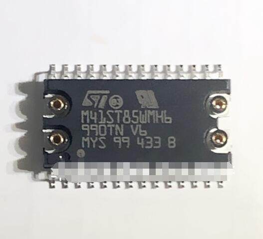
The M41ST85WMH6F is a Real-Time Clock (RTC) module with an integrated 256 Kbit serial I2C bus EEPROM. This device is manufactured by STMicroelectronics and is designed to provide accurate time and date information in various electronic systems. Let's break down its functions, pin assignments, and hardware connections:
Functions:
-
Real-Time Clock (RTC):
- The M41ST85WMH6F provides accurate timekeeping, including seconds, minutes, hours, day, date, month, and year information.
-
256 Kbit Serial I2C Bus EEPROM:
- This integrated EEPROM allows for non-volatile storage of data, making it suitable for storing configuration information, event logs, or other critical data.
-
Battery Backup:
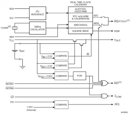
- The device typically includes a built-in power-fail sense circuitry and a 32.768 kHz crystal, often used to maintain timekeeping functionality during power outages or when the main supply is disconnected.
Pin Assignments:
While I can't provide the exact pin assignments without the datasheet, typically, the M41ST85WMH6F would have pins dedicated to the following functions:
-
Power Supply and Ground:
- These pins are essential for powering the device and are usually labeled VCC and GND.
-
I2C Bus Interface:
- SDA (data line) and SCL (clock line) pins for communicating with the host microcontroller or system.
-
32.768 kHz Crystal Connection:
- Pins for connecting an external 32.768 kHz crystal oscillator.
-
Battery Backup:
- Pins for connecting an external battery or supercapacitor used for backup power.
-
Address Pins:
- These pins might be used for setting the I2C device address.
Hardware Connections:
Connection requirements can vary based on the specific application and the rest of the system design. However, a typical hardware connection setup might look like this:
-
Power Supply:
- Connect the VCC and GND pins to the appropriate power supply and ground connections.
-
I2C Bus Connection:
- Connect the SDA and SCL pins to the corresponding lines on the microcontroller or I2C bus of the host system.
-
Clock Crystal:
- Connect the crystal oscillator to the designated pins.
-
Battery Backup:
- If battery backup is required, connect the backup power source to the specified pins.
-
Pull-up Resistors:
- Ensure that proper pull-up resistors are connected to the SDA and SCL lines in accordance with the I2C bus specifications.
It's crucial to refer to the datasheet of the M41ST85WMH6F for the exact pin assignments, electrical characteristics, and hardware connection details, as this information will provide the most accurate and specific guidance for integrating the device into a system. If you have the device, its datasheet should provide comprehensive information on connecting and using the module within your design.